ASME – PRINCIPLES OF GAUGES AND FIXTURES
The American Society of Mechanical Engineers (ASME) provides standards for dimensioning and tolerancing across various engineering applications, including the development of gages and fixtures. These principles, outlined in ASME Y14.43, provide guidelines to ensure that gages and fixtures are manufactured to a high level of precision, helping to ensure that the components they measure meet the required tolerances.
Below are the main principles of dimensioning and tolerancing for gages and fixtures according to ASME standards:
1. Design for Interchangeability
Gages and fixtures are designed for repeated use, meaning they must meet strict tolerance levels to ensure consistent measurement accuracy. Design specifications must consider interchangeability, ensuring that each gage can measure parts within the required tolerance limits, even with slight variations in production.
- Example: A company manufactures wheel axles and uses cylindrical gages to check shaft diameter. The gage design must ensure that all gages are manufactured to the same diameter, so any gage can be used to check any axle without causing dimensional discrepancies.
2. Applying GD&T (Geometric Dimensioning & Tolerancing) Principles
ASME standards, particularly Y14.5, guide the application of GD&T principles on gages and fixtures. This includes specifying tolerances for form, orientation, location, and runout, which are critical for precise alignment and measurement.
- Example: When designing a fixture for a hole in a component, GD&T standards specify the perpendicularity of the hole relative to a reference plane. This fixture will check if the hole is perpendicular to that plane, ensuring that holes are not misaligned when assembled with other parts.
3. Using Material Condition Modifiers (MMC, LMC, RFS)
Material condition modifiers are essential in defining the tolerance ranges for different material conditions. MMC (Maximum Material Condition) and LMC (Least Material Condition) are applied to set tolerance limits, especially for functional gages that check parts under assembly conditions.
- Example: A hole in a component may need to be inspected at MMC to ensure it isn’t too small. The gage for inspecting this hole will be sized at the maximum allowable dimension, ensuring that if the gage fits through the hole, the hole meets tolerance requirements.

Example: A hole in a component may need to be inspected at MMC (Maximum Material Condition) to ensure it is not too small. The gage used to inspect this hole will be sized at the maximum allowable dimension, ensuring that if the hole is large enough for the gage to pass through, it meets the required tolerances.
4. Functional Gaging Principles
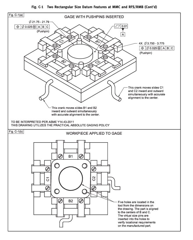
Functional gages are designed to simulate the mating conditions of parts in an assembly. They ensure that if a part fits the gage, it will also fit its mating part. This principle ensures that critical features, such as holes and shafts, meet the required tolerances.
- Example: A go/no-go gage is used to check the size of shafts when fitting into bearings. The “go” end of the gage must fit the shaft if it meets the minimum size requirement, while the “no-go” end cannot fit if the shaft is too large, ensuring that the shaft will not cause issues when assembled into the bearing.
5. Establishing Datum Reference Frames
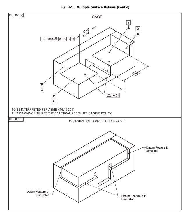
Datum reference frames are essential reference points in GD&T and are necessary for consistently locating parts in fixtures and gages. The accurate selection and alignment of datums help maintain measurement consistency and accuracy.

Example: When designing a fixture for a flat surface on a metal block, reference planes (datums) will be established from specific edges of the block to accurately position it within the fixture. These datum points help consistently align the metal block throughout the measurement and inspection process.
6. Tolerance Accumulation and Stack-Up Analysis
When designing fixtures, it is necessary to consider tolerance stack-up, which refers to how individual tolerances accumulate during assembly. Accumulated tolerances are evaluated to ensure that the final dimensions remain within acceptable limits.
- Example: In the assembly of a part comprising multiple components, the fixture must ensure that the total tolerances from each component do not distort the overall size. A component may have a tolerance of ±0.1 mm, but if 10 parts are assembled together, the cumulative tolerance could be ±1 mm. This analysis ensures that the overall inspection fixture does not exceed the tolerance limits.
7. Tolerances for Inspection and Verification
Gages must also comply with the necessary tolerances for inspection. This includes establishing a verification process for the gages to ensure they remain accurate over time due to high usage frequency.
- Example: A gage used to check the internal diameter of bearings needs to have a tighter tolerance than the actual diameter of the bearings to ensure high accuracy. If the bearing requires a tolerance of ±0.05 mm, the gage may need to achieve a tolerance of ±0.01 mm to accurately verify the bearing dimensions within the allowable tolerance range.
8. Calibration and Regular Maintenance
Regular calibration and maintenance of gages and fixtures are essential to ensure they meet ASME standards over time, minimizing measurement errors and maintaining the reliability of the measurement system.
- Example: A pin gage used daily to check hole diameters may wear over time. To avoid measurement inaccuracies, this gage needs to be checked and recalibrated regularly, for example, every six months, to ensure that the accuracy of hole measurements does not deteriorate.
TASVINA is a company specializing in providing comprehensive solutions for design and machining, as well as the measurement and inspection of Gauges & Fixtures.
Contact: Nguyễn Xuân Cảnh (Mr. Orion) (SALE MANAGER)
- Phone: (+84) 905.648.436
- Email: tas.info@tasvina.com


